At ARCA you will find the right control valve for each process step in the boiler of the power plant.
1) Feed water control valve
With this control valve, the level in the boiler drum is regulated so that boiler feed water is continuously available in the boiler for steam generation. In order to compensate for the difference between the characteristic curve of the feed water pump and the operating characteristic of the boiler system, the characteristic curve of the feed water control valve must be designed accordingly.
(Recommended : ECOTROL® Series 8C, 6H, Series 350, 380)
2) Feed water startup valve
The boiler drum is filled by this control valve when the system is started up. Since a large differential pressure and cavitation have to be mastered during start-up, this valve is subject to high stress and thus wear. Therefore, this often small valve is equipped with a hardened multi-stage trim and is located in parallel with the feed water control valve, which must then be designed for maintaining the level.
(Recommended : ECOTROL® Series 8C, 6H, Series 190 and Series 350)
3) Burner control valve
This valve regulates the supply of natural gas to the gas burner or the fuel oil to the oil burner on the boiler. During gas operation, special attention has to paid on the flow characteristics and the noise reduction. During fuel oil operation this valve operates as a back pressure control valve keeping the pressure upstream of the oil burner constant.
(Recommended : ECOTROL® Series 8C, 6N)
4) Blowdown valve
This valve quickly opens for a brief moment to drain a small quantity of boiler feed water for desludging the boiler water drum. Hard internal parts are required to withstand the high differential pressure, flashing conditions and abrasion that prevail. The sealing edges of this control valve are subject to wear, which is why we recommend installing an additional shut-off valve here.
(Recommended : ECOTROL® Series 8C, 6H, Series 190, Series 350, 380)
5) Boiler start-up control valve
The start-up control valve typically blows steam through a silencer system into the atmosphere when the boiler is started. Since the steam expands with a high pressure reduction, this valve usually has an asymmetric design.
(Recommended : ECOTROL® Series 8C, 6H, Series 350, 380)
6) Soot blower control valve
The walls of the heat exchangers in the boiler are steam-cleaned of soot particles to optimize heat transfer efficiency inside the boiler. To this end, soot blower control valves feed live steam to the soot blower nozzles with minimum actuating time. (series: 6H, 190, 350, 380)
(Recommended : ECOTROL® Series 6H, Series 350, 380)
7) Air preheater control valve
The burner air is preheated to optimize the effectiveness of the combustion process. The temperature of the burner air is determined by the steam fed to the air preheater via this control valve.
(Recommended : ECOTROL® Series 8C, 6N)
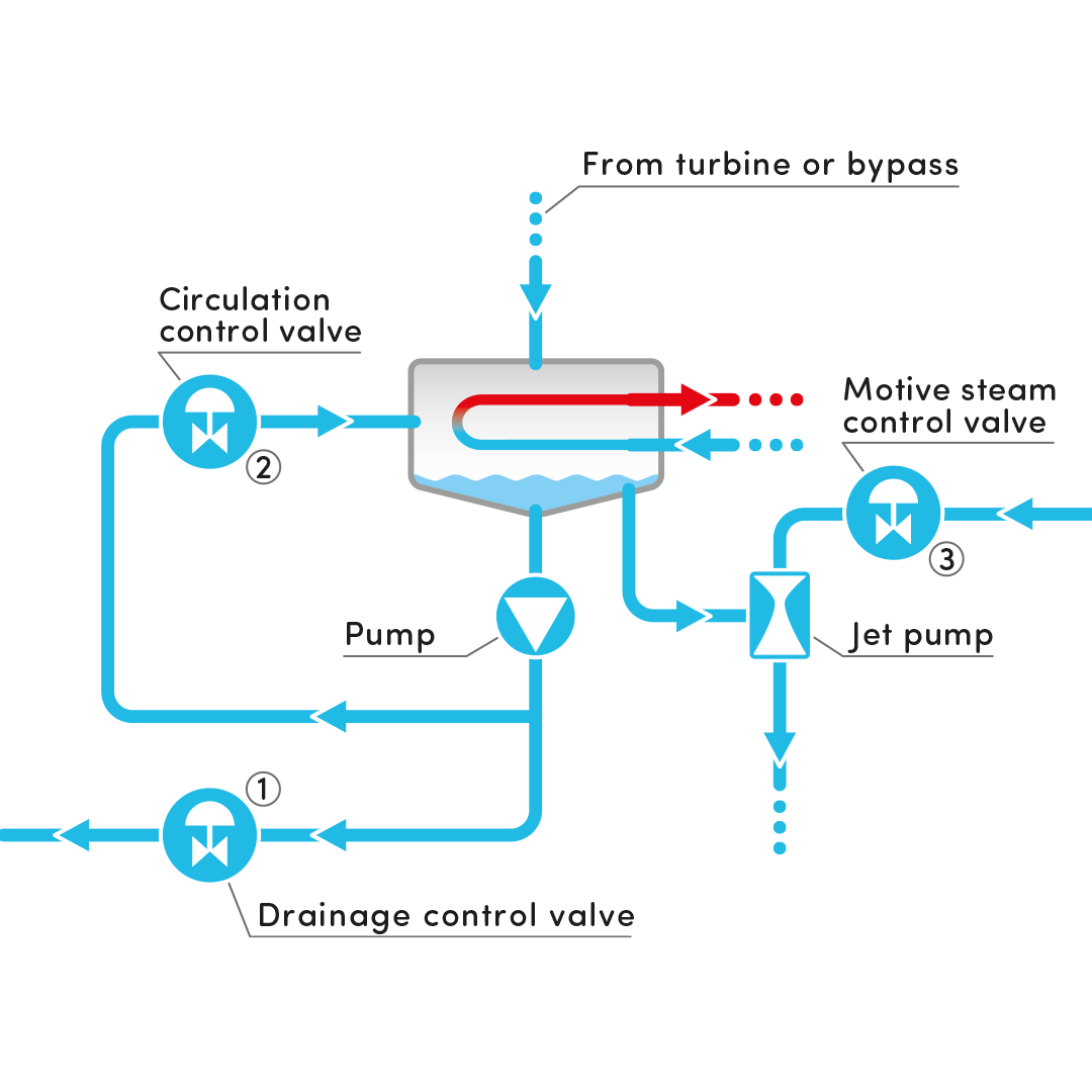
8) 3-way mixing valve (variant I)
Superheating the steam of the steam turbines while they are running increases plant efficiency and prevents the turbine blades from becoming damaged by condensed drops of liquid. For better energy utilization of the generated steam, a secondary superheater is installed in power plants with higher steam pressures. The heat transferred to the superheater varies greatly due to fluctuating loads and soot deposits in particular. The temperature of the superheater must therefore be regulated. The superheated steam is passed through a pipe coil by means of the 3-way mixing valve, which is located in the water-filled part of the steam drum. The colder drum water with the saturated steam temperature thus cools the superheated steam. (series: 200, 220)
(Recommended : Series 200,220)
8) Boiler injection cooler (variant II)
Another way of controlling the superheater temperature is usually implemented in new systems by injecting boiler feed water with a desuperheater.
(Recommended : Series 590)